Circular Array of 3D Elements |
  
|
Icon |
Ribbon |
|---|---|
|
3D Model > Operations > Array > Circular Array Assembly (3D) > Assembly > Array > Circular Array Sheet Metal (3D) > Advanced > Array > Circular Array Surfaces > Advanced > Array > Circular Array Primitives > Advanced > Array > Circular Array Support Geometry > Copy > Array > Circular Array |
Keyboard |
Textual Menu |
<3AR> |
Operation > Array > Circular Array |
The command creates arrays by placing copies of source objects on a circle about a selected axis.
Main concepts of creating a linear array are described in the Classes of Arrays of 3D Elements section.
In order to create a circular array, perform following steps upon calling the command:
1.Choose a type of the array to be created (![]() array of constructions,
array of constructions, ![]() array of operations,
array of operations, ![]() array of bodies,
array of bodies, ![]() array of faces,
array of faces, ![]() array of fragments);
array of fragments);
2.Select source objects of the array;
3.Define an axis of the array;
4.Select start and end points of rotation (optional step);
5.Define a number of copies, step and total angle in the first forward direction;
6.Apply the parallel offset (optional step);
7.Define a number of copies in the first reverse direction (optional step);
8.Define a directional vector and other parameters of array in the second and third directions in the similar way as it was defined in the first direction (optional step);
9.Apply a layout and half-step shifts (optional step);
10.Apply limitations and exclusions (optional step);
11.Define optional parameters of the array (optional step);
12.Confirm the operation (![]() in the automenu or in the header of the parameters window).
in the automenu or in the header of the parameters window).
General Parameters

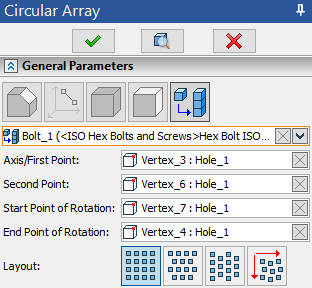
The General Parameters tab of command's parameters window contains the Axis/First Point input box. It is connected to the following automenu option:
|
<A> |
Select axis of rotation |
Activating the input box activates the automenu option and vice versa. In result, filters for selecting ![]() points,
points, ![]() axes and
axes and ![]() directions become active on the filter toolbar, so you can select
directions become active on the filter toolbar, so you can select ![]() the desired object in the 3D scene or in the model tree. An icon representing a type of a selected element, its name and name of its parent operation (in case of selecting a geometric entity) are displayed in the Axis/First Point input box.
the desired object in the 3D scene or in the model tree. An icon representing a type of a selected element, its name and name of its parent operation (in case of selecting a geometric entity) are displayed in the Axis/First Point input box.
Upon selecting a ![]() direction or an
direction or an ![]() axis, a selected object fully defines an axis of array, so that no additional selection is required.
axis, a selected object fully defines an axis of array, so that no additional selection is required.
Upon selecting a ![]() point, the additional Second Point input box appears below the Axis/First Point input box. The Second Point input box is connected to the following automenu option:
point, the additional Second Point input box appears below the Axis/First Point input box. The Second Point input box is connected to the following automenu option:
|
<S> |
Select second point of Axis |
Activating the input box activates the automenu option and vice versa. In result, filters for selecting ![]() points become active on the filter toolbar, so you can select
points become active on the filter toolbar, so you can select ![]() the desired object in the 3D scene or in the model tree. An icon representing a type of a selected element, its name and name of its parent operation (in case of selecting a geometric entity) are displayed in the Second Point input box.
the desired object in the 3D scene or in the model tree. An icon representing a type of a selected element, its name and name of its parent operation (in case of selecting a geometric entity) are displayed in the Second Point input box.
A direction from first point to second is considered an axis of the array
You can ![]() Clear the selection in the Axis/First Point and Second Point input boxes individually, using buttons located in the right side of each input box, or clear both input boxes at once, using one of the following automenu options:
Clear the selection in the Axis/First Point and Second Point input boxes individually, using buttons located in the right side of each input box, or clear both input boxes at once, using one of the following automenu options:
|
<K> |
Cancel axis of rotation selection |
Either the total angle or the step of the array can be defined by two points. These points can be selected upon activation of the Start Point of Rotation and End Point of Rotation input boxes in the General Parameters tab of the command's parameters window or using the following automenu options:
|
<T> |
Select starting point of Rotation |
|
<O> |
Select ending point of Rotation |
Activating the input box activates the automenu option and vice versa. In result, filters for selecting ![]() points become active on the filter toolbar, so you can select
points become active on the filter toolbar, so you can select ![]() the desired object in the 3D scene or in the model tree. An icon representing a type of a selected element, its name and name of its parent operation (in case of selecting a geometric entity) are displayed in aforementioned input boxes.
the desired object in the 3D scene or in the model tree. An icon representing a type of a selected element, its name and name of its parent operation (in case of selecting a geometric entity) are displayed in aforementioned input boxes.
You can ![]() Clear the selection in the Start Point of Rotation and End Point of Rotation input boxes individually, using buttons located in the right side of each input box, or clear both input boxes at once, using one of the following automenu options:
Clear the selection in the Start Point of Rotation and End Point of Rotation input boxes individually, using buttons located in the right side of each input box, or clear both input boxes at once, using one of the following automenu options:
|
<L> |
Cancel selection of points for Rotation |
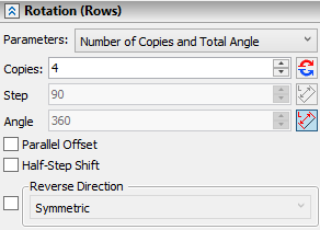
The Rotation (Rows) tab containing parameters of array in the first direction is located below the General Parameters tab in the command's parameters window.

The Parameters drop-down list containing following combinations of array's parameters is located in the top of the tab:
•Number of Copies and Step;
•Total Angle and Step;
•Number of Copies and Total Angle.
Depending on the selected combination only two of the three input boxes located below (Copies, Step and Angle) are accessible, while the value in the third input box is calculated automatically.
By default, forward direction of array is the clockwise direction, when looking along axis of array.You can ![]() Reverse it if necessary, using the button, which is located to the right side of the Copies input box.
Reverse it if necessary, using the button, which is located to the right side of the Copies input box.
If Start and End Points of Rotation are selected, the system automatically applies one of the options, which defines ether the Step or the total Angle (depending on the combination selected in the Parameters drop-down list) as an angle between planes passing through the axis of rotation and these points, thus values in the corresponding input boxes are non-editable. These options can be disabled or enabled manually, using ![]() By Two points buttons located to the right side of the Step and Angle input boxes. Both options can not be applied for Angle and Step at once.
By Two points buttons located to the right side of the Step and Angle input boxes. Both options can not be applied for Angle and Step at once.
The Half-Step Shift and Parallel Offset checkboxes are located below the Angle input box.
The detailed information on parallel offset is available in the Classes of Arrays of 3D Elements section.
The detailed information on half-step shift is available in the Layout and Half-Step Shift in Arrays of 3D Elements section.
Bottommost parts of each directional tab in the command's parameters window contain the Reverse Direction checkbox combined with the drop-down list. The drop-down list contains two options: Symmetric and Value. The checkbox is disabled by default, so copies in each direction (rows, columns and height) are positioned on the same side in relation to the source object (forward direction). Enabling the checkbox applies the Symmetric option, so the number of copies in reverse direction becomes equal to number of copies in forward direction. Upon selecting the Value option, the input box for typing in the custom number of Copies in reverse direction appears below the drop-down list.
More information on the reverse direction of arrays is available in the Classes of Arrays of 3D Elements section.
Radial Translation (Columns) and Axial Translation (Height)
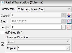
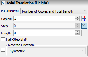
The Radial translation (Columns) and Axial Translation (Height) tabs containing parameters of array in the second and third directions are located below the Rotation (Rows) tab of the command's parameters window.


Both tabs contain the same set of parameters listed below. Geometrical meaning of these parameters is described in the Classes of Arrays of 3D Elements section.
The Parameters drop-down list containing following combinations of array's parameters is located in the top of the each directional tab:
•Number of Copies and Step;
•Total Length and Step;
•Number of Copies and Total Length.
Depending on the selected combination only two of the three input boxes located below (Copies, Step and Length) are accessible, while the value in the third input box is calculated automatically.
By default, the forward direction of the radial translation is pointed outside from array's axis; the forward direction of the axial translation coincides with a direction of array's axis. You can ![]() Reverse directions if necessary, using buttons, which are located to the right side of Copies input boxes in each directional tab.
Reverse directions if necessary, using buttons, which are located to the right side of Copies input boxes in each directional tab.
By default, even if the selected combination of parameters allows manual input of array's step, a value in the Step input box is non-editable due to automatic application of the option, which defines step as the length of the directional vector. The similar option is available (but disabled by default) for the Length parameter. The length of a radial translation's directional vector is a distance between an axis of rotation and a source object's center of mass. The length of an axial translation's directional vector is a length of array's axis.
These options can be disabled or enabled manually, using the ![]() By Vector button, which is located to the right side of the corresponding parameter's input box. Both options can not be applied at once for Length and Step in the same direction.
By Vector button, which is located to the right side of the corresponding parameter's input box. Both options can not be applied at once for Length and Step in the same direction.
The Half-Step Shift checkbox is located below the Length input box.
The detailed information on half-step shift is available in the Layout and Half-Step Shift in Arrays of 3D Elements section.
Bottommost parts of each directional tab in the command's parameters window contain the Reverse Direction checkbox combined with the drop-down list. This option is described above.
Topics in this section:
•Edit Circular Array of 3D Elements
See Also:
•Types of Arrays of 3D Elements
•Classes of Arrays of 3D Elements
•Limitations and Exclusions in Arrays of 3D Elements
•Referencing 3D Elements of Array