Angle by Four Points |
  
|
Angular dimension by four points is basically a variation of angular dimension by two straight line segments, where the segments are defined indirectly by endpoints.
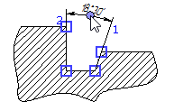
In order to create such dimension, upon calling the ![]() Dimension command, activate the following automenu option:
Dimension command, activate the following automenu option:
|
<F> |
Angular Dimensions by 4 Points |
Upon activating this option, sequentially select four points by clicking them with ![]() . Tips displayed in the status bar suggest the order of points selection. First and second points define the first segment, third and fourth points define the second segment. Characteristic points of graphic lines, 2D nodes and intersections of construction lines can be selected as points. Selecting an intersection of construction lines results in automatic creation of a connected 2D node there.
. Tips displayed in the status bar suggest the order of points selection. First and second points define the first segment, third and fourth points define the second segment. Characteristic points of graphic lines, 2D nodes and intersections of construction lines can be selected as points. Selecting an intersection of construction lines results in automatic creation of a connected 2D node there.
Selected couples of points should not lay on parallel lines. Otherwise, the dimension won't be created.
2D nodes may also be selected using the following automenu option:
|
<N> |
Select Node |
Upon activating this option, clicking ![]() anywhere in drawing select a nearest 2D node.
anywhere in drawing select a nearest 2D node.
Upon selecting four points, regardless of the method of selection, the preview of the dimension appears, while dimension line and value positioning, dimension symbol, dimension linking options and common options of 2D elements creation commands become available in the automenu. Dimension line follows the cursor along the imaginary line segments defined by the selected points, while the dimension value follows the cursor along the dimension line. Witness lines connect dimension line with first and third points.
Imaginary lines defined by the selected points split the plane into quarters. By default, the dimension is based on a quarter arbitrarily selected by the system. Depending on the cursor position (inside or outside the selected quarter), the dimension either shows the angle of the selected quarter, or the total angle of the remaining three quarters.
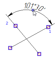
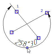
Same as when creating an angle between two lines, you can select another quarter using the following automenu option:
|
<Z> |
Change Dimension Orientation (for angular dimension) |
Clicks ![]() on the icon of this option in the automenu sequentially switch the dimension between all possible quarters.
on the icon of this option in the automenu sequentially switch the dimension between all possible quarters.
Pressing the hotkey of this option selects the quarter, where the cursor is currently located. If the cursor is outside drawing window, the hotkey doesn't work.
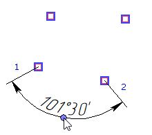
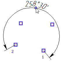
Set the desired positions of dimension line and value by moving the cursor, and confirm it by pressing ![]() or <Enter>. The dimension will be created. Upon creating a dimension, the command remains in the mode of creating angular dimensions by four points.
or <Enter>. The dimension will be created. Upon creating a dimension, the command remains in the mode of creating angular dimensions by four points.