Manual Hatch Contours Input |
  
|
In order to define hatch contours manually, activate the following automenu option, upon calling the ![]() Hatch command:
Hatch command:
|
<A> |
Manual Contour input mode |
If the manual contour input mode was used for the last time, then this option will be active, upon calling the command. Pressing option's icon or hot key for the second time switches the command to the automatic contours search mode.
In the manual input mode you can sequentially define segments of the contour bounded by 2D nodes. Alternatively, you can select a closed curve as a full contour. When creating or editing a hatch, its contours are highlighted in blue. Same as for the graphic lines creation, manual hatch contour input may be performed using free or linked drawing modes. Use the following automenu option, in order to toggle between free and linked drawing:
|
<Ctrl>+<F> |
Upon defining a closed contour, you can either add another contour for the current hatch in the same way as adding the first one, or confirm the hatch creation using the following automenu option:
|
<Ctrl>+<Enter>, <End> |
Finish input |
Defining segments of hatch contour
Manual contour input starts with selecting a starting node. Move the cursor over the desired node. If object snappings are enabled, the node will be highlighted, and the node symbol will appear near the cursor. Then press ![]() or <Enter> to select the node. This way you can select existing 2D nodes or create new ones at intersection of construction lines and endpoints of graphic lines.
or <Enter> to select the node. This way you can select existing 2D nodes or create new ones at intersection of construction lines and endpoints of graphic lines.
Within the linked drawing mode ![]() , clicking
, clicking ![]() an empty space of the drawing window selects the nearest existing 2D node or intersection of construction lines.
an empty space of the drawing window selects the nearest existing 2D node or intersection of construction lines.
Within the free drawing mode ![]() , clicking
, clicking ![]() an empty space of the drawing window creates a free 2D node there.
an empty space of the drawing window creates a free 2D node there.
You may also use the following automenu option for selecting existing 2D nodes:
|
<N> |
Select Node |
Upon activating this option, pressing ![]() anywhere in drawing selects the nearest node regardless of the drawing mode.
anywhere in drawing selects the nearest node regardless of the drawing mode.
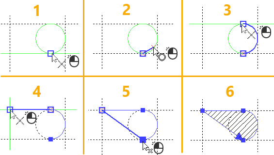
Upon selecting a starting node, you should either select an ending node of the current segment using the same methods (in such case the segment will go go straight from starting to ending node), or select a curve, which will define the shape of the segment. Such curve may be either a graphic line, one of whose endpoints coincides with the starting node of the segment, or a construction line passing through the starting node. Move the cursor over the desired line. If the line can be selected, it will be highlighted and the icon indicating the line type will appear near the cursor. Then press ![]() or <Enter> to select the line.
or <Enter> to select the line.

If a graphic line coincides with a construction line, then pressing![]() or <Enter> over them without using the linetype-specific automenu option select the construction line. If you want the system to select graphic lines in such cases, enable the Select graphic lines when creating hatch contours checkbox in system options (Options > Snap > Snap).
or <Enter> over them without using the linetype-specific automenu option select the construction line. If you want the system to select graphic lines in such cases, enable the Select graphic lines when creating hatch contours checkbox in system options (Options > Snap > Snap).
Construction lines may also be selected using the following automenu options:
|
<L> |
Select Line |
|
<C> |
Select Circle |
|
<E> |
Select Ellipse |
|
<S> |
Select Spline |
Upon activating any of these options, pressing ![]() anywhere in drawing selects the nearest object of the corresponding type. Splines selection option also allows to select 2D paths, offset curves and function splines.
anywhere in drawing selects the nearest object of the corresponding type. Splines selection option also allows to select 2D paths, offset curves and function splines.
Graphic lines may also be selected using the following automenu option:
|
<Space> |
Select Graphic Line |
Activating this option instantly selects a graphic line, one of whose endpoints coincides with the starting node of the current segment. If the starting node of the segment coincides with endpoints of multiple graphic lines, then one nearest to the cursor will be selected.
If the starting node of the current segment lays on a closed construction curve, then the trajectory of the segment along such curve is selected depending on which direction provides the shortest path from the starting node to the cursor position at the moment of selecting the curve. You can switch it to the opposite direction using the following automenu option:
|
<Z> |
Change arc direction |

Upon selecting a graphic line, the defining of the current segment ends, and the opposite endpoint of the selected line becomes the ending node of the segment.
Upon selecting a construction line, you have to manually define an ending node. To do so move the cursor over a 2D node laying on the selected line, or over an intersection of the selected line and another construction line, and press ![]() or <Enter>. Upon selecting an intersection, a 2D node is automatically created there. Upon selecting an ending node, the defining of the current segment ends.
or <Enter>. Upon selecting an intersection, a 2D node is automatically created there. Upon selecting an ending node, the defining of the current segment ends.
The ending node of the current segment becomes also the starting node of the next segment. This way you can sequentially define any number of segments.
Wrong node selection can be canceled using the Cancel last element selection option, which is available in the menu invoked by pressing ![]() anywhere within drawing window.
anywhere within drawing window.
Wrong segment definition can be canceled using the following automenu option:
|
<BackSpace> |
Delete last contour segment |
Pressing <Esc> cancels all segments of the current contour. If the starting node of the current contour is node selected, pressing <Esc> cancels all contours of the current hatch. If none of the contours are yet defined, it exits the command.
If you select the starting node of the first segment as the ending node of the last segment, then the contour gets closed. If the ending node of the last segment doesn't coincide with the starting node of the first segment you can quickly close the contour using the following automenu option:
|
<Home> |
Close Contour |
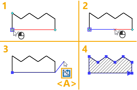
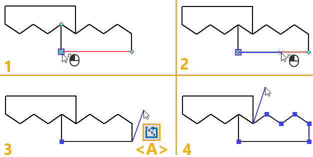
If the last segment is defined using a graphic line, and such line is a part of graphic lines chain, then you can quickly use the following lines of the chain as contour segments using the following automenu option:
|
<A> |
Find contour automatically |
If the chain is closed, the hatch contour will be closed.

If the chain has branches, then the contour will be defined up to the nearest branching.

If the starting node of the current segment coincides with the branching point of the chain, then this option will have no effect.
Using a closed curve as hatch contour
Instead of selecting a starting point of the first segment, you can select a closed curve by moving the mouse over it and pressing ![]() or <Enter>. In such case, the full contour will be defined by the selected curve. This way you can use both construction and graphic lines. Construction lines may also be selected using the following automenu options:
or <Enter>. In such case, the full contour will be defined by the selected curve. This way you can use both construction and graphic lines. Construction lines may also be selected using the following automenu options:
|
<C> |
Create Full Circle Contour |
|
<E> |
Select Ellipse Contour |
|
<S> |
Select Spline or Polyline Contour |
Upon activating any of these options, pressing ![]() anywhere in drawing selects the nearest object of the corresponding type. Splines selection option also allows to select 2D paths, offset curves and function splines.
anywhere in drawing selects the nearest object of the corresponding type. Splines selection option also allows to select 2D paths, offset curves and function splines.

When using the splines selection option, open curves may be selected. In case of selecting an open curve, the contour will be closed automatically by adding a straight connection between the starting and the ending point of the selected curve.