Sketch Line Parameters |
  
|
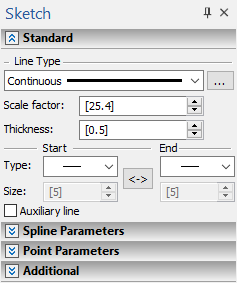
Parameters of sketch elements are displayed in ![]() parameters tool window (see below) and in
parameters tool window (see below) and in ![]() parameters dialog. Parameters dialog of a sketch line is identical to parameters dialog of any other graphic line. Parameters dialog of an existing line can be called in the command standby mode either from line's contextual menu, or by double clicking the line in the drawing window or in the Model elements window. Moreover, the following option is available in the automenu of the Sketch command:
parameters dialog. Parameters dialog of a sketch line is identical to parameters dialog of any other graphic line. Parameters dialog of an existing line can be called in the command standby mode either from line's contextual menu, or by double clicking the line in the drawing window or in the Model elements window. Moreover, the following option is available in the automenu of the Sketch command:
|
<P> |
Set graphic line parameters |
It invokes the dialog, where you can set parameters to be applied to all sketch lines created next. The content of the dialog is identical to the content of the existing line's parameters dialog. In addition, there is the Color for current page only checkbox. Enabling the checkbox makes the Color selected in the dialog applicable only to elements created on the current page of the document.
2D nodes created via the Point command have the same parameters dialog, as free 2D nodes created by other commands.
When working with any of the Sketch command's options, the Style tab is displayed at the top of the parameters window. The tab contains the standard set of graphic lines' display parameters, same as described in the Graphic Line Parameters section. Below this tab there are tabs containing geometrical parameters of the created element. Names and number of such tabs may vary depending on the type of element. Geometrical parameters for elements of particular types are described separately in sections describing certain options of the Sketch command. General principles of defining geometrical parameters are described below.

Defining geometrical parameters
When creating a sketch, geometrical parameters of elements should be defined, such as coordinates of characteristic points and some dimensions of created geometrical shapes. Input boxes of geometrical parameters are displayed in the parameters window. Positions of characteristic points can be specified either by placing the cursor over a desired position in the drawing window and pressing ![]() , or by typing values in the parameters window. When pointing positions of points with the cursor, you can use object snappings. By default, values in the parameters window correspond to the current position of the cursor in the drawing window. As you type a value via keyboard, it is inputted into the active input box. The active input box is indicated by highlighting of its value. You can activate another input box either by placing the cursor over it and pressing
, or by typing values in the parameters window. When pointing positions of points with the cursor, you can use object snappings. By default, values in the parameters window correspond to the current position of the cursor in the drawing window. As you type a value via keyboard, it is inputted into the active input box. The active input box is indicated by highlighting of its value. You can activate another input box either by placing the cursor over it and pressing ![]() , or by using its hot key. A hot key of an input box is displayed in the tooltip, when you move the cursor over this box. Upon inputting a value via keyboard, the checkbox of the inputted parameter gets enabled, thus fixing the value, so it no longer depends on cursor position. In order to confirm input, just press <Enter> or click
, or by using its hot key. A hot key of an input box is displayed in the tooltip, when you move the cursor over this box. Upon inputting a value via keyboard, the checkbox of the inputted parameter gets enabled, thus fixing the value, so it no longer depends on cursor position. In order to confirm input, just press <Enter> or click ![]() anywhere in the drawing window.
anywhere in the drawing window.
When creating elements, you can use both Cartesian and polar coordinates and their combinations, so you can specify different options for arranging points in the most convenient way.
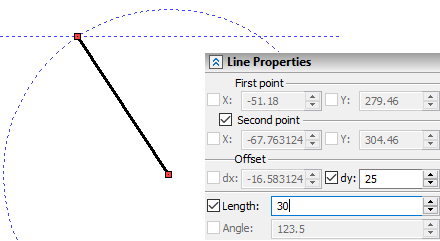
For example, when specifying the second point of a straight line segment, you can type in the offset value and the length of the radius vector. In this case, auxiliary elements appear in the drawing: circle with the center at the beginning of the segment and the given radius and a horizontal line spaced from the first point of the segment by a distance equal to the specified offset along the Y axis (dy).

The points of intersection of a circle and a straight line define possible variants of the location of the second point of a segment for given parameters. In the drawing, this is reflected as a free node that moves, when the mouse moves from one point of intersection of the circle and the line to the other. When you select the necessary point and click ![]() , you can finish the creation of the segment.
, you can finish the creation of the segment.
When you change the sketch option, only those parameters that are relevant for this option are displayed in the parameters window. For example, the list of geometric parameters of a polygon differs significantly from the list of center arc parameters.

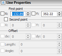
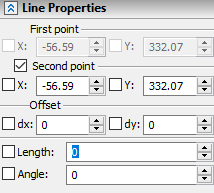
The list of coordinates of characteristic points and geometric sizes in the parameters window also depends on the stage of values input. For example, when constructing a line by two points, only the X Y coordinates of the first point are initially available. Upon defining the position of the first point, the coordinates of the second one, as well as offsets, length and angle become available.

