Array of 3D Elements by Path |
  
|
Icon |
Ribbon |
|---|---|
|
3D Model > Operations > Array > Array by Path Assembly (3D) > Assembly > Array > Array by Path Sheet Metal (3D) > Advanced > Array > Array by Path Surfaces > Advanced > Array > Array by Path Primitives > Advanced > Array > Array by Path Support Geometry > Copy > Array > Array by Path |
Keyboard |
Textual Menu |
<3AP> |
Operation > Array > Array by Path |
The command creates arrays, using guide curves for defining positions of elements.
Main concepts of creating an array by path are described in the Classes of Arrays of 3D Elements section.
In order to create an array by path, perform following steps upon calling the command:
1.Choose a type of the array to be created (![]() array of constructions,
array of constructions, ![]() array of operations,
array of operations, ![]() array of bodies,
array of bodies, ![]() array of faces,
array of faces, ![]() array of fragments);
array of fragments);
2.Select source objects of the array;
3.Select a guide curve in the first direction
4.Select a start point in the first direction (optional step);
5.Define a number of copies, step and total length in the first direction;
6.Choose a copy placement option in the first direction (optional step);
7.Define a guide curve, start point and parameters of array in second and third directions in the similar way as it was defined in the first direction (optional step);
8.Apply limitations and exclusions (optional step);
9.Define optional parameters of the array (optional step);
10.Confirm the operation (![]() in the automenu or in the header of the parameters window).
in the automenu or in the header of the parameters window).
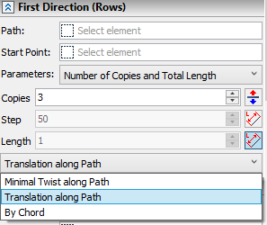
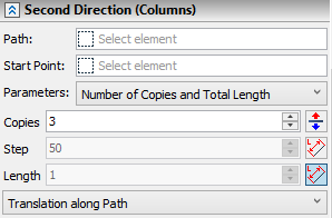
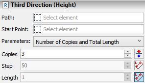
Apart from the General Parameters (selecting a type of the array and source objects), Limitations, Exclusions and Options tabs the command's parameters window contains three tabs similar to each other:
•First Direction (rows);
•Second Direction (columns);
•Third Direction (height).


These tabs contains the similar sets of parameters described below. The geometrical meaning of these parameters is described in the Classes of Arrays of 3D Elements section.
Defining a Path, number of Copies, Step and Length in the First Direction (rows) is mandatory for creating an array. Two of the latter three parameters are defined by user, the third one is calculated automatically from values of two others.
A guide curve can be selected upon activating ![]() the Path input box on the corresponding directional tab. These input boxes are connected to following automenu options:
the Path input box on the corresponding directional tab. These input boxes are connected to following automenu options:
|
<T> |
Select first guide curve |
|
<O> |
Select second guide curve |
|
<J> |
Select third guide curve |
Activating the input box activates the automenu option and vice versa. In result, filters for selecting ![]() wires (
wires (![]() 3D profiles,
3D profiles, ![]() faces,
faces, ![]() edges,
edges, ![]() loops,
loops, ![]() 3D paths) become active on the filter toolbar, so you can select
3D paths) become active on the filter toolbar, so you can select ![]() the desired object in the 3D scene or in the model tree. An icon representing a type of a selected element, its name and name of its parent operation (in case of selecting a geometric entity) are displayed in the Path input box. You can
the desired object in the 3D scene or in the model tree. An icon representing a type of a selected element, its name and name of its parent operation (in case of selecting a geometric entity) are displayed in the Path input box. You can ![]() Clear the selection, using the button located in the right side of the input box.
Clear the selection, using the button located in the right side of the input box.
Upon selecting a ![]() face, a sequence of edges forming its boundaries is used as the guide curve.
face, a sequence of edges forming its boundaries is used as the guide curve.
The direction of array is defined by a direction of a guide curve. You can ![]() Reverse Direction, using the button located to the right side of the Copies input box.
Reverse Direction, using the button located to the right side of the Copies input box.
Additionally a Start Point can be selected for each direction upon activating![]() the eponymous input box on the corresponding directional tab of command's parameters window. These input boxes are connected to following automenu options:
the eponymous input box on the corresponding directional tab of command's parameters window. These input boxes are connected to following automenu options:
|
<S> |
Select start point |
|
<B> |
Select start point |
|
<K> |
Select start point |
Activating the input box activates the automenu option and vice versa. In result, filters for selecting ![]() points become active on the filter toolbar, so you can select
points become active on the filter toolbar, so you can select ![]() the desired object in the 3D scene or in the model tree. An icon representing a type of a selected element, its name and name of its parent operation (in case of selecting a geometric entity) are displayed in the Start Point input box. You can
the desired object in the 3D scene or in the model tree. An icon representing a type of a selected element, its name and name of its parent operation (in case of selecting a geometric entity) are displayed in the Start Point input box. You can ![]() Clear the selection, using the button located in the right side of the input box.
Clear the selection, using the button located in the right side of the input box.
One of the following combinations of array's parameters can be selected in the Parameters drop-down list, which is located below start point input boxes in each directional tab of the command's parameters window:
•Number of Copies and Step;
•Total Length and Step;
•Number of Copies and Total Length.
Depending on the selected combination only two of the three input boxes located below (Copies, Step and Length) are accessible, while the value in the third input box is calculated automatically.
By default, even if the selected combination of parameters allows manual input of total length's value, the Length input box is inaccessible due to automatic application of the option, which defines total length as the length of the guide curve. This option can be disabled, using the ![]() By Path button, which is located to the right side of the Length input box. The similar button is located to the right side of the Step input box, allowing to define the Step as the relation of Length to the number of Copies. Both options can not be applied at once for Length and Step in the same direction.
By Path button, which is located to the right side of the Length input box. The similar button is located to the right side of the Step input box, allowing to define the Step as the relation of Length to the number of Copies. Both options can not be applied at once for Length and Step in the same direction.
When using an open Path in combination with a Start Point, the guide curve is trimmed, so that start point's projection becomes a start of a guide curve.
Copy placement options for fist and second directions can be selected in drop-down lists, which are located in the bottom of directional tabs. Following placement options are available:
•Minimal Twist along Path;
•Translation along Path;
•By Chord.
Copy placement options are not available for the third direction. Upon selecting a path for the third direction, the Translation along Path becomes the only available option for the first and second directions.
When using the By Chord placement option, the Number of Copies and Step becomes the only available combination of parameters for this direction.
The detailed information on copy placement options is available in the Classes of Arrays of 3D Elements section.
Topics in this section:
•Edit Array of 3D Elements by Path
See Also:
•Types of Arrays of 3D Elements
•Classes of Arrays of 3D Elements
•Limitations and Exclusions in Arrays of 3D Elements
•Referencing 3D Elements of Array