Distance by Cone |
  
|
In order to create a linear dimension based on two non-parallel straight line segments, upon calling the ![]() Dimension command, activate the following automenu option:
Dimension command, activate the following automenu option:
|
<O> |
Cone Dimension |
Activating this option sets selection filters in such way, that only straight line segments can be selected. Then you should select two segments in any order by clicking them with ![]() . If selected segments are parallel to each other, then the resulting dimension will be similar to simple distance between two parallel lines. If selected segments are not parallel to each other, then they are considered silhouette edges of a cone side projection. In this case, the dimension measures the distance between the endpoints of the selected lines, in the direction normal or parallel to the axis of the cone. Initially, the system arbitrarily selects one of the four possible pairs of points of measurement, and the measurement direction is normal to the axis. The following automenu option may be used for sequential switching between possible combinations of measurement direction and points of measurement.
. If selected segments are parallel to each other, then the resulting dimension will be similar to simple distance between two parallel lines. If selected segments are not parallel to each other, then they are considered silhouette edges of a cone side projection. In this case, the dimension measures the distance between the endpoints of the selected lines, in the direction normal or parallel to the axis of the cone. Initially, the system arbitrarily selects one of the four possible pairs of points of measurement, and the measurement direction is normal to the axis. The following automenu option may be used for sequential switching between possible combinations of measurement direction and points of measurement.
|
<M> |
Change Dimension type |
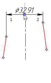
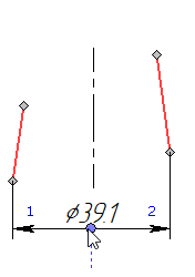
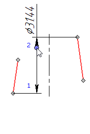
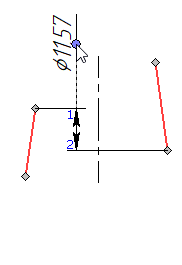
Thus, you can dimension a cone base on a projection view without creating additional nodes at endpoints of lines.
Alternatively, line segments may be selected using the following option, which appears in the automenu upon entering the ![]() cone dimension creation mode:
cone dimension creation mode:
|
<L> |
Select line |
Upon activating this option, clicking ![]() anywhere in the drawing selects a line segment nearest to the point of clicking. A single activation of the option allows selecting two segments in a row.
anywhere in the drawing selects a line segment nearest to the point of clicking. A single activation of the option allows selecting two segments in a row.
Upon selecting segments in any of the ways described above, the preview of the dimension appears. The the dimension line follows the cursor in the direction normal to the direction of measurement, and the dimension value follows the cursor along the dimension line. The dimension line and value positioning, dimension symbol, dimension linking options and common options of 2D elements creation commands appear in the automenu. Set the desired positions of the dimension line and value by moving the cursor, and confirm the input by pressing ![]() or <Enter>. The dimension will be created. Upon creating a dimension, the command stays in the cone dimensions creation mode.
or <Enter>. The dimension will be created. Upon creating a dimension, the command stays in the cone dimensions creation mode.

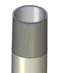
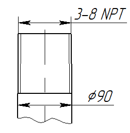
If selected cone lines are projected from a 3D model of a conic thread created using the ![]() Thread command, then the dimension designation inherited from the thread parameters will be shown instead of the dimension value.
Thread command, then the dimension designation inherited from the thread parameters will be shown instead of the dimension value.
