Inserting Roughness, GD&T Symbols, Fragments and Pictures into Text |
  
|
Among other things, you can insert into the text:
•picture.
Insert roughness or GD&T symbols
When editing the text content in a 2D or 3D view window, the symbols are inserted into the text using the automenu:
|
<Ctrl>+<F8> |
Insert Roughness |
|
<Ctrl>+<F9> |
Insert GDT |
In addition, these commands are available in the contextual menu (Insert ![]()
![]() Roughness... <Ctrl>+<F8>, Insert
Roughness... <Ctrl>+<F8>, Insert ![]()
![]() GD&T... <Ctrl>+<F9>).
GD&T... <Ctrl>+<F9>).
When editing the text content in the editor, these commands are available in the Standard toolbar, as well as in the drop-down menu (Insert > Roughness..., Insert > Tolerance ...).
After calling one of the listed commands, a dialog of roughness or GD&T feature control frame parameters appears on the screen. In the dialog, you should set the necessary symbol parameters and click OK, after which the symbol will be inserted into the text.
Detailed information about roughness symbols is available in the Roughness section.
Detailed information about feature control frame is available in the GD&T Feature Control Frame section.
The created symbol can be edited by clicking ![]() on the symbol in the text content editing mode (both in the 2D window and in the editor) and selecting one of the following items in the context menu that appears:
on the symbol in the text content editing mode (both in the 2D window and in the editor) and selecting one of the following items in the context menu that appears:
•![]() Parameters...
Parameters...
Calls the roughness or GD&T feature control frame parameters dialog.
•Size and Position...
Calls the Object Parameters dialog.
When editing the text content in a 2D or 3D view window, fragments are inserted into the text using the automenu:
|
<Ctrl>+<F10> |
Insert Fragment |
In addition, this command is available in the contextual menu (Insert ![]()
![]() Fragment... <Ctrl>+<F10>).
Fragment... <Ctrl>+<F10>).
When editing the text content in the editor, this command is available in the Standard toolbar, as well as in the drop-down menu (Insert > Fragment...).
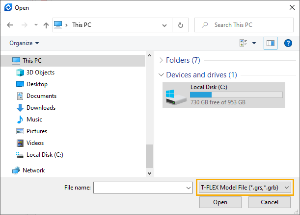
Calling the command invokes the standard Windows Explorer window for selecting a file. Working with the Explorer window is carried out in the same way as described in the Open Model section.

As a fragment, you can select T-FLEX CAD Model File (*.grs, *.grb) or T-FLEX CAD Remark File (*.grn). If you try to use a file of a different format, the fragment will not be inserted.
Select the necessary file and click Open. If there are no external variables in the selected file, then the fragment insertion will be completed. Otherwise, the external variables of the fragment dialog will open. Set the required variable values and click OK to finish inserting the fragment.
As a result, an image of the first page of the fragment drawing will appear in the text. If the first page of the fragment drawing is empty, then the image in the text will also be empty. Upon adding an image to the first page of a fragment, the system will suggest to update the links in the document in which the fragment is inserted. After updating the links, the image in the text will be updated.
The inserted fragment can be edited by clicking ![]() on it in the text content editing mode (both in the 2D window and in the editor) and selecting one of the following items in the contextual menu:
on it in the text content editing mode (both in the 2D window and in the editor) and selecting one of the following items in the contextual menu:
•![]() Parameters...
Parameters...
Calls the fragment parameters.
•![]() Variables...
Variables...
Calls the external variables of the fragment dialog
•Size and Position...
Calls the Object Parameters dialog.
When editing the text content in a 2D or 3D view window, pictures are inserted into the text using the automenu:
|
<Ctrl>+<F7> |
Insert Picture |
In addition, this command is available in the contextual menu (Insert ![]()
![]() Picture... <Ctrl>+<F7>).
Picture... <Ctrl>+<F7>).
When editing the text content in the editor, this command is available in the Standard toolbar, as well as in the drop-down menu (Insert > Picture...).
Calling the command invokes the standard Windows Explorer window for selecting a file. Working with the Explorer window is carried out in the same way as described in the Open Model section.

As a picture, you can choose image files of various formats, as well as T-FLEX CAD documents.
Unlike inserting a fragment, when using a T-FLEX CAD document as an image, you cannot set the values of external variables. However, it allows to choose the page displayed in the text.
Select the necessary file and click Open. As a result, the image of the first page of the selected file will appear in the text. To select a different page, use the picture parameters dialog (see below).
You can also copy an image from the text in *.rtf format to the clipboard and then ![]() Paste <Ctrl>+<V> from the buffer into the T-FLEX CAD text (except string text).
Paste <Ctrl>+<V> from the buffer into the T-FLEX CAD text (except string text).
The inserted picture can be edited by clicking ![]() on it in the text content editing mode (both in the 2D window and in the editor) and selecting one of the following items in the contextual menu:
on it in the text content editing mode (both in the 2D window and in the editor) and selecting one of the following items in the contextual menu:
•![]() Parameters...
Parameters...
Calls the picture parameters dialog.
•Size and Position...
Calls the Object Parameters dialog.
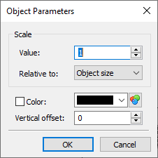
In the text content editing mode (both in the editor and in 2D or 3D view windows), the contextual menu of roughness symbols, GD&T formlimits symbols, fragments and pictures inserted into the text contains the Size and Position... item, which opens a dialog of the following type:

In the dialog, you can set the following parameters of the object inserted into the text:
•Scale
This group of parameters contains the scale Value input box and a drop-down list, in which you can select, Relative to what the entered Value is applied to. By default, objects are inserted into text with a scale of "1" relative to the Font Size. As a result, the height of the inserted object is equal to the height defined in the text font parameters. If necessary, you can set the scale relative to the size of the object. For pictures and fragments, the size of the object is the size of the inserted picture in the source file. For symbols, the object size is the font size set in the roughness or tolerance parameters dialog.
•Color
By default, images and fragments are inserted into the text with the same colors as in the source file, and the symbols are inserted with the color set on the General tab in the roughness or GD&T feature control frame parameters dialog. If necessary, you can choose a different color in the Size and Position... dialog. The color selection is performed in the same way as described in the Color section. To apply the selected color, enable the Color checkbox. For a fragment, the selected color is applied to all lines at once, even if they initially have different colors. Using this parameter is not recommended for the image, because it leads to the replacement of the image with a frame of the selected color.
•Vertical offset
The distance from the current line of text to the lower border of the inserted object.
See also: