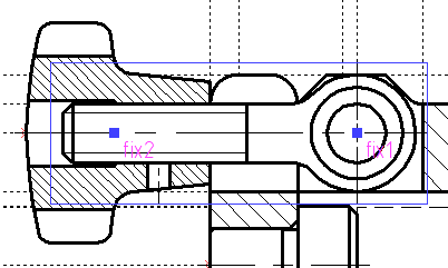
Example of 2D Assembly > Fragments' Fixing Elements |
  
|
Before starting to create an assembly drawing, it is necessary to think over its structure. The main thing is to determine the requirements for its parametric capabilities: what exactly do you want to modify later, which parts will make up the drawing, what kind of hierarchy of fragments is assumed.
If an assembly is created using the Top-Down approach, before creating assembly drawing, you should create parts drawing. However, don't rush with their creation. First, think over the design of the assembly, from which fragment you will begin to assemble the drawing, which parts will be attached later, where the fixing points of the fragments should be located. Depending on these factor, you should correctly define fixing elements in part drawings. Otherwise, you may create a good looking part drawings, but encounter problems, when trying to build an assembly from them.
In the our drill jig example, fragments of drawn parts (Body, Lid, Fork) and standard handles are positioned using fixing vectors defined by two points in fragment documents. Such points may be specified in using different methods, in our case they're connected 2D nodes at intersections of construction lines. In general, the presence or absence of a parametric link between points of fixing vector and graphic elements of the fragment doesn't matter. In our example such link is established using fragments' external variables, which allows to change fragments' geometry automatically upon changing values of assembly variables.
Upon inserting a fragment into an assembly using fixing vector, it can positioned in two ways - by two points or by point and angle. In the first case, you should sequentially specify two 2D nodes of the assembly: the origin of the fixing vector gets coincided with the first node and the direction of the vector gets pointed to the second node. In the second case, the origin is positioned in the same way and the direction is specified arbitrarily.
In result, position and orientation of fragment in assembly may change depending on position of specified nodes, but the geometry of fragment remains unchanged. Assembly nodes may also be created at intersections of construction lines or inherited from other fragments. Nodes from fragments are created automatically, when you select characteristic points of a fragment for positioning another fragment. If you need nodes from fragment not coinciding with points of graphic lines, you should create such nodes in fragment's document and name them. Upon inserting the fragment into assembly, such nodes can be used for positioning other fragments.
Fragments of standard parts, which have versions of different length with same diameter (bolt, screws, bushings, rest buttons, pins), are positioned using fixing points on projections, where their length is visible, or using fixing vectors (as described above) on other projections. A fixing point is defined in fragment as an intersection of a horizontal an a vertical construction lines, where position of such lines is defined by specifically named external variables. All graphic elements of fragment's drawing, which are supposed to be displayed in assembly, are created as children of fixing points' parent lines. In our example each of the mentioned fragments have two fixing points. In general the number of points may be different. Upon inserting a fragment into an assembly, the corresponding number of assembly nodes should be specified: fixing points of the fragment get coincided with the specified nodes, and the geometry of the fragment gets recalculated in accordance with nodes' positions.
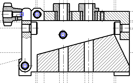
Let's explore the order of fragments insertion on the front view of the drill jig assembly.
The design of the jig is defined by the geometry of the workpiece. Therefore, before inserting fragments, we have drawn the contour of the workpiece with construction lines in assembly drawing. Dimensions of the workpiece are defined by external variables L, l, H, C, A. Then offsets by the gap value were made.
Actual position of the workpiece represented by dashed graphic lines in the final drawing is slightly shifted down compared to these construction lines due to ceiling of body dimensions introduced for manufacturability reasons.
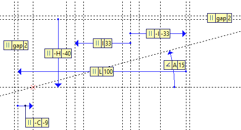
Rest buttons have been inserted first, since they are in direct contact with the workpiece and their dimensions affect the geometry of drawn parts. The vertical position of the rest buttons is defined by the center of the right face of the workpiece. If the face is too small, the rest button even of the smallest diameter may stick out above and below the face, thus disallowing the correct assembling of the jig. Therefore, the check for face height has been implemented. The height is calculated in the expression of the hr using the measure() function, which yields the distance along the Y axis between named 2D nodes created at intersections of construction lines forming the contour of the workpiece. In the expression of the hrcheck variable the height value is compared with minimal standard diameter of rest button. If the height is lower, the error() function outputs an error message informing the user, that workpiece dimensions should be changed. For positioning of the rest buttons, the horizontal construction line has been created at Yrest distance from the upper edge of the workpiece, where Yrest is the half of the right face's height rounded with precision up to 0.5 using the round() function. Fixing points of each rest button are positioned at intersections of this line with contours of the workpiece and with gaps offsets.
The frec() and val() functions are used for finding a minimal allowed height of liner bushings in the internal database, considering the diameter of holes to be drilled. The height of the bushings defines the thickness of the lid (Hlid). The frec() function finds a number of record fulfilling the specified conditions, and the val() function yields the content of the specified column for a record with the specified number.

Bushings are inserted by fixing points at intersections of construction lines defining the thickness of the lid with axes of holes to be drilled.
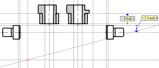
Then the Body and Lid fragments have been inserted by fixing vector at the upper left angle of the workpiece.
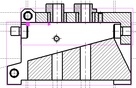
The Fork has been inserted by the node from the Body and the Handle has been inserted by the node from the Fork. Pins and the pressure screw have been inserted by centers of corresponding holes in the Body and Lid.
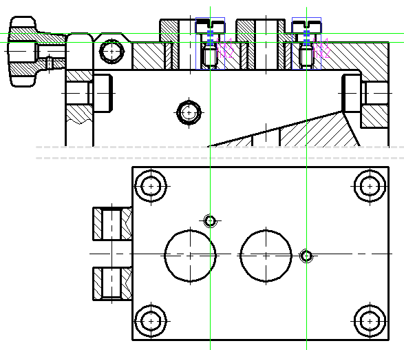
Locking screws should be placed at a standard distance from axes of bushings. In the expression of the Ascrew variable this distance is selected automatically from the internal database, using the frec() and val() functions, considering the diameter of holes to be drilled in the workpiece. For the second hole this distance should be offset in direction angled in relation to the front view plane. Therefore, for positioning of the second locking screw on the front view, the Lid was placed on the top view first. The position of holes for these screws in the Lid is defined by the Ascrew external variable, which is automatically linked with the eponymous assembly variable upon insertion. Then the vertical line has been constructed through the center of the screw hole on the top view and used for positioning the screw on the front view. Screws are inserted by fixing points at intersections of screw holes axes with the upper edge of the lid and the locking recess of drill bushes.
Finally, the eye bolt is fixed by the center of the hole in the lid and the node from the handle fragment.
