Create Face Blend |
  
|
|
To create the operation, perform the following steps, upon calling the
1.Select a blend mode and specify its parameters (optional step).
2.Select left faces (left wall).
3.Select right faces (right wall).
4.Specify a type of blend (optional step).
5.Select a spine (optional for the Rolling Ball type, mandatory for other types of blend).
6.Specify a shape of blend surface's cross-section (optional step).
7.Specify boundary conditions (optional step).
8.Select limit planes (optional step).
9.Specify a solution (optional step).
10.Specify a trimming method (optional step).
11.Specify a result topology (optional step)
12.Specify an inside tight corners processing method (optional step).
13.Specify other options (optional step).
14.Confirm the operation |
The blending mode can be switched using the buttons at the top of the parameters window at any stage of working with the command. Following modes are available.
The Radius mode is used by default.
Below you can set the parameters of the selected mode. The ![]() button can be used for specifying the graph of corresponding parameter's change along the length of the spine.
button can be used for specifying the graph of corresponding parameter's change along the length of the spine.
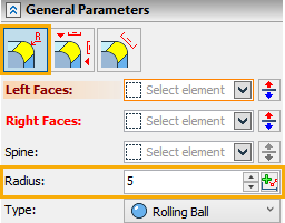
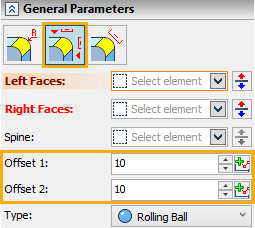
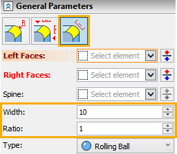
Normally, the operation is defined beginning with selecting the sets of faces between which the blend will be constructed.
To select a face, select the corresponding input field - Left Faces or Right Faces.
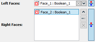
Face selection is done using the mouse in the 3D view window.
The selected faces of the left wall are highlighted in green by default, the right ones - yellow. Settings of the highlighting colors are done in the system customization dialog box. The current face highlighting color is reflected in a color box on the tab tag for each set.
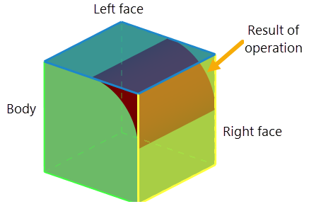
A decorator is drawn in the middle of each face, shaped as an arrow, marking the side of the face adjacent to the blend surface. In a general case, two walls make four quadrants, each being suitable for constructing a blend surface. In order to select a quadrant to create the blend surface, you can use the Reverse ![]() button for each face.
button for each face.
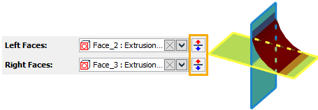
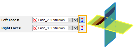
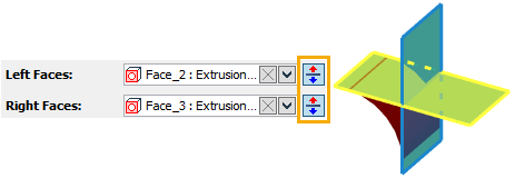
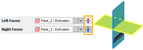
For solid bodies, the direction of an arrow is determined automatically. For surface bodies, the direction of faces has to be controlled manually by the user.
To exclude a face from a wall set, simply select it in the list in the parameters window on the respective field and press ![]() Delete Element from the List button.
Delete Element from the List button.
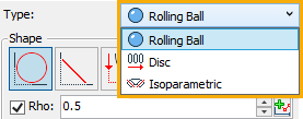
The type of blend can be selected from the Type drop-down list in the parameters window. Following types are available:
The Rolling Ball type is used by default.
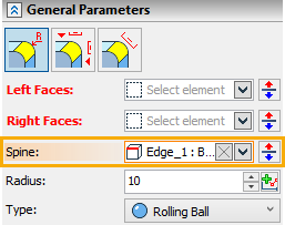
In order to select a spine, click ![]() the Spine box in the parameters window, and then click
the Spine box in the parameters window, and then click ![]() the desired element in 3D scene or in model tree. The
the desired element in 3D scene or in model tree. The ![]() Reverse button changes the direction of spine length measurement, which is important, when blend parameters are set using graphs.
Reverse button changes the direction of spine length measurement, which is important, when blend parameters are set using graphs.
The shape of the blend surface's cross-section can be selected using buttons in the Shape group of controls in the parameters window. Following shapes are available:
The conic shape is used by default.
For conic and continuous curvature, additional controls for specifying the shape parameters may appear below.
For conic shape, the Convexity (Rho) can be additionally specified. To do so, enable the eponymous checkbox, and then type a value into the adjacent input box. Alternatively, you can define a graph of convexity change along the length of the spine, using the ![]() button.
button.

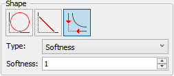
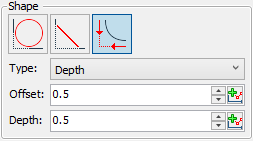
For Continuous Curvature, you should select a Type of curvature (Softness or Depth). Input boxes of selected type's parameters are available below. Parameters of depth may also be ![]() defined via graphs.
defined via graphs.
All types of boundary conditions are defined along the specially selected edges. In order to select such edges, click ![]() the empty space of the Edges list in the parameters window, then click
the empty space of the Edges list in the parameters window, then click ![]() the desired edges in 3D scene or in model tree. Names of selected edges and their parent objects are displayed in the box. In order to to select an edge in the list, click
the desired edges in 3D scene or in model tree. Names of selected edges and their parent objects are displayed in the box. In order to to select an edge in the list, click ![]() its row. You may
its row. You may ![]() Expand,
Expand, ![]() Collapse or
Collapse or ![]() Clear the list, as well as
Clear the list, as well as ![]() Delete the selected element from the list, using buttons located to the right of the list.
Delete the selected element from the list, using buttons located to the right of the list.
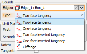
Boundary conditions are specified individually for each of the selected edges. First, select an edge in the Edges list, then select its boundary condition in Type list. Following types of boundary conditions are available:
The Two-face tangency is used by default.
Keep in mind, that boundary conditions can work only in connection with compatible geometrical parameters of the blend surface that are defined by the blending mode and cross-section shape.
Thus, if the cross section parameters prevent the blend surface from reaching a bounding edge, then the boundary condition on tangency to one or both walls is impossible. Vise versa, if an inverted tangency boundary condition is selected, then the appropriate radius of the blend surface is such, that the blend is not reaching the bounding edge or the wall itself in the zone of such edge.
In order to select a limit plane, click ![]() the First or the Second box in the parameters window, and then click
the First or the Second box in the parameters window, and then click ![]() the desired plane of planar face in 3D scene or in model tree.
the desired plane of planar face in 3D scene or in model tree.

If you want to use only one limit plane, use the First box. Specify both the First and Second limit planes only when you want to use two limit planes at the same time.
The ![]() Reverse button changes the side of limiting the blending surface in relation to the selected plane.
Reverse button changes the side of limiting the blending surface in relation to the selected plane.
If multiple blend surfaces are possible for the selected faces, then you can create either of them, or only a single one.
Following options are available in the Solutions drop-down list:
![]() All
All
This option is used by default, so all of the possible blend surfaces are created.
![]() Use Adjusting Point
Use Adjusting Point
Upon selecting this option, the Node box appears below and gets automatically activated, so you can select ![]() a 3D node in 3D scene or in model tree. The blend result will only contain the surface nearest to the selected node.
a 3D node in 3D scene or in model tree. The blend result will only contain the surface nearest to the selected node.
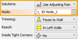
Following methods of trimming the blend surface are available in the Trimming drop-down list:
The Faces to Wall method is used by default.
Following result topology options are available in the Result drop-down list:
|
Separate Body |
|
Trim Walls |
|
In Left Walls |
|
Create New Body |
The In Left Wall option is used by default.
The algorithm's for processing inside tight corners allow creating blends in the areas where the value of the curvature radius of the sidewalls is less than the blend radius. This option is available only for rolling ball blending by a conical section of a constant radius.
the method of inside tight corners processing can be selected in the Inside Tight Corners drop-down list. Following methods are available, similar to the ![]() Edge Blend command:
Edge Blend command:
The No option, meaning that blend can not be created in inside tight corners, is used by default.

Following options may be specified at the bottom of the command's parameters window:
•Accuracy
The tolerance to within which the adjacency between faces or edges is considered smooth.
See Also: