Measure Relations between two Elements |
  
|
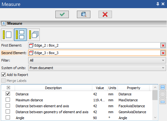
The mode of measuring relations between two elements can be activated using the following button located in the upper section of the ![]() Measure command's parameters window:
Measure command's parameters window:
|
<2> |
Measure relation between two elements |
After enabling this mode, the First Element box gets automatically activated in the command's parameters window. As long as this box is active, clicking an element of almost any type with ![]() in 2D window, 3D window or 3D model tree selects such elements as the first object of measurement. Upon selecting the first element, the Second Element box gets automatically activated in the command's parameters window, so you can select the second object of measurement in the similar way to selecting the first one. Names and icons of selected elements are displayed in said boxes. In order to change the selection, activate the desired box by clicking it with
in 2D window, 3D window or 3D model tree selects such elements as the first object of measurement. Upon selecting the first element, the Second Element box gets automatically activated in the command's parameters window, so you can select the second object of measurement in the similar way to selecting the first one. Names and icons of selected elements are displayed in said boxes. In order to change the selection, activate the desired box by clicking it with ![]() and then select another element. The selection can be cleared using the
and then select another element. The selection can be cleared using the ![]() Clear button located at the right side of the box.
Clear button located at the right side of the box.
If two elements are selected at the moment of calling the command, then the command gets launched in this mode.
If a single element is selected at the moment of entering this mode, then such element is automatically used as the first object of measurement.
If two elements are selected at the moment of entering this mode, then such elements are automatically used as the first and second objects of measurement.
If more than two elements are selected at the moment of entering this mode, then the first two selected elements are automatically used as objects of measurement and the rest of the elements get unselected.
The set of relationships to be measured depends on types of selected objects.

Measuring angles between 3D elements
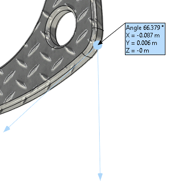
Let's elaborate measurement of angles. Angle is measured between directional vectors of two 3D objects. Below you can see the list of 3D objects, for which a directional vector can be defined (and, therefore, the angle can be calculated). What will be selected as the directional vector, is explained for each object after the hyphen:
•for a 3D path, edge or open 3D profile lying on a straight line – the line direction;
•for a 3D path, edge or open 3D profile lying on an ellipse (circle) – the vector directed from the center of the ellipse (circle) normal to the plane of the ellipse (circle);
•for a flat 3D profile; workplane; flat face; an operation body consisting of one face lying in a plane – the normal to the plane;
•for a cylindrical worksurface; cylindrical face; 3D profile lying on a cylinder; an operation body consisting of one face lying on a cylinder – the axis of the cylinder;
•for a 3D profile or face, lying on a cone; an operation body consisting of one face lying on a cone – the axis of the cone;
•for a toroidal worksurface; 3D profile or face lying on a torus; an operation body consisting of one face lying on a torus – the axis of the torus.
Directional vectors listed above are also used as axes, when calculating relations involving axes (distance between axes, distance between element and axis, distance between geometry of element and axis).
The angle between curves is measured as the angle between their tangents.
•The angle is measured for two curves between tangents at the first intersection point of the curves.
•If there is no intersection, it is measured at the intersection point of the tangent of the first curve and the second curve.
•If the tangent does not intersect the second curve, the angle is measured at the point where the tangents intersect.

See Also:
•Measurement Coordinate System
•Labels of Measurement Results
•Save Measurement Results in 3D Model Tree
•3D Node by Measurement Results
•3D Path by Measurement Results