Parameters Dialog of 3D Path |
  
|
Parameters Dialog of 3D Path |
|
When creating a new 3D path its parameters dialog can be invoked using the option:
|
<P> |
Set entity parameters |
The parameters dialog for an existing path can be invoked by double clicking ![]()
![]() a path or by selecting the
a path or by selecting the ![]() Parameters command in its contextual menu.
Parameters command in its contextual menu.
3D path parameters dialog always contains following tabs:
•Common
This tab is described below.
•Transformations
Contains information about transformations applied to the node. This tab has the same functionality as the Parameters window described for the Transformations command, except that it doesn't allow to apply symmetry and snap transformations to reference elements and doesn't contain information about Mate Transformations (it can be found in the separate tab of the dialog).
•Mate Transformations
Contains information about mate transformations applied to the node. This tab has the same functionality as the eponymous tab of the Parameters window described for the Transformations command.
Additionally, depending on the type of the path, the dialog might contain one of the following tabs:
•Path Parameters
•Offset
•Operation
These tabs have the same functionality as the Parameters window has, when the 3D path being created. Depending on the type of the path, a tab tab might contain the full set of said parameters or some of them. Detailed descriptions are available in sections describing particular 3D path types.
Moreover, there is the Set as default checkbox located at the bottom of the dialog regardless of the active tab. If you enable this checkbox, parameters of the selected element will be applied as defaults for all elements of the same type created in future.
Common Parameters of 3D Path
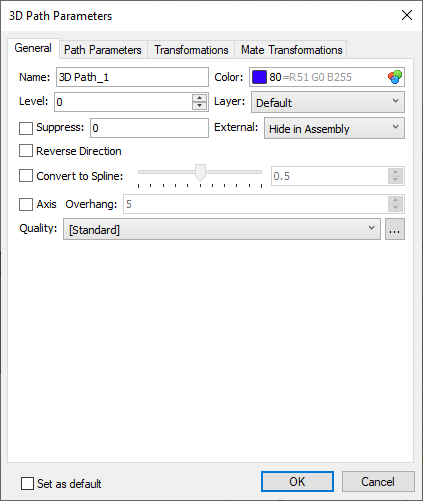
Name
Each element of a model have a unique name. User can type name manually. In this case the system checks if typed name is unique. If typed name is already assigned to another element in this document, the changes are not applied. If user didn't input a custom name, the system generates name automatically. More information about automatically generated names can be found in the Names Customization for 3D Elements chapter.
Color
The color of path's representation in the 3D scene. Color can be selected in the same way as described in the Color chapter.
Level
This parameter is described in the Levels chapter.
Layer
This parameter is described in the Layers chapter.
Suppress
This option can be used for excluding a path from the 3D model generation. Suppressed path isn't displayed in the 3D scene. Enabling the Suppress checkbox excludes a path from the model generation and sets the "1" value in the corresponding input box. Disabling the checkbox includes a path into the model generation and sets the "0" value in the corresponding input box. Value may also be typed manually or defined by a real variable for controlling the suppression via Parametrization. A path is suppressed, if a variable's value isn't zero. Any whole values apart from zero are replaced by "1". Fractional values are not allowed.
Keep in mind, that suppression of a parent element leads to errors upon regenerating its child elements.
External
Two options are available in the drop-down list: Hide in Assembly and One Level. If the model is used as a 3D fragment, then paths with One Level option applied are accessible in the assembly. The position of such path is fully defined by the position of its 3D fragment. The parameters dialog of a 3D path belonging to a 3D fragment in an assembly contains only one tab - Common. A name of a 3D fragment is added to a name of a path as a prefix. The One level option can also be applied to paths in assemblies, that will allow using such paths in assemblies of higher level.
Reverse Direction
A 3D path has a direction. Depending on the method of path creation, the direction might be defined by the order of support elements selection, by their geometry or arbitrarily. The direction might affect geometry of path's child elements. Enabling this checkbox switches the direction to opposite one. By default, path directions are not indicated in the 3D scene. If you want to enable the indication of path directions, enable the Arrow on ends of 3D paths/3D profiles option (Document Parameters > Document > 3D > 3D).
Convert to Spline
A path might geometrically consist of several connected lines with vertices at connection points. If necessary, you can convert a path into a spline, using this checkbox. The checkbox is disabled by default, so the conversion is not applied. Enabling the checkbox turns a path into a single spline with the intermediate vertices being removed. The approximation accuracy can be set in range from 0.0 (Rough) to 1.0 (Precise) using the slider or the input box. In certain cases, such paths are more suitable then those consisting of several lines (for instance, in the Loft operation).
Axis
Instead of creating an axis using the 3D Axis command, a path created by other commands can be converted into axis. To do so, enable this checkbox. Disabling the checkbox converts an axis into a generic 3D path. Axes are displayed in dash-dot lines in the 3D scene.
Overhang
This parameter is available for editing, when the Axis checkbox is enabled (see above). It is the distance of axis extension beyond both ends of the initial path.
Quality
The quality of displaying the path in the 3D window. The drop-down contains options similar to described in the Image Quality chapter.
If you want to use one of the system presets as a template for customizing user-defined parameters, select a preset in the drop-down and click the ![]() button located to the right side of the drop-down. The Mesh Quality dialog will appear with parameters of a selected preset. Enable the User Settings checkbox to edit them.
button located to the right side of the drop-down. The Mesh Quality dialog will appear with parameters of a selected preset. Enable the User Settings checkbox to edit them.
See also: