Value of Dimension |
  
|
The Value tab of the ![]() Dimension command's parameters window contains following controls:
Dimension command's parameters window contains following controls:

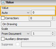
This parameter defines, how the nominal dimension value will be calculated. You can select one of the following options in the drop-down list:
•None. The value is not displayed on the dimension.
•Auto. The value is calculated automatically based on drawing elements on which it is created. This allows a dimension to automatically change its value upon any modification to the drawing.
•Manual. The value is inputted manually by the user into the input box located to the right of the drop-down list. Regardless of drawing modifications, such dimension value will stay unchanged. This option is used when you need to introduce a dimension value in the drawing, that does not match the automatically calculated dimension value. When inputting the value, you can use contextual menu commands, for example, in order to define an angle in degrees, minutes and seconds, or to define value via a variable.
•Manual with Corrections. The dimension value is inputted manually by the user similar to the previous case. However, on the drawing the value of such dimension will be recalculated taking into consideration the specified scale and correction (see below).
•Driving. The value is also inputted manually by the user, and it not only affects the dimension display, but also defines the geometry of dimension's source objects. Seem more in the Driving 2D Dimension and Driving 3D Dimension sections.
•By Source Lines. This option is available for 2D dimensions, drawn on the elements of any associative copy. Upon selecting this option, the dimension value is defined by the original elements of the copy (selecting the Auto option for such dimensions, would result in calculating the value on the basis of those elements of the copy to which the dimension is attached to). The By Source Lines option can be used, for example, for dimensioning lines of detail views without taking into account the scale of the view.
•From lines. This option is available for dimensions created on the 2D projection lines (or their associative copies), if such lines represent a thread created in 3D model using the ![]() Thread or command or the threaded hole option of the
Thread or command or the threaded hole option of the ![]() Hole command. Also, this option is available for 3D dimensions based on threaded surfaces of the 3D model. When using this option, the thread designation inherited from 3D operation parameters is displayed instead of the dimension value.
Hole command. Also, this option is available for 3D dimensions based on threaded surfaces of the 3D model. When using this option, the thread designation inherited from 3D operation parameters is displayed instead of the dimension value.
•From 3D parent. This option is available for dimensions created on the 2D projection lines (or their associative copies), if there are 3D dimensions drawn on faces, edges and vertices of the original 3D model represented by those lines. Upon selection of this option, the text and parameters of the 2D dimension will be inherited from the 3D dimension.
Regardless of the option selected in this parameter's drop-down list, after creating a dimension, clicking a dimension value with ![]() directly in drawing invokes the value input toolbar
directly in drawing invokes the value input toolbar ![]() , where you can type in a new value via keyboard. The Set "Driving" parameter when editing checkbox is enabled by default in system options (Options > Constraints and dimensions > Create Dimensions Automatically). In result, any 2D dimension automatically becomes a driving one, when the user manually changes its value this way.
, where you can type in a new value via keyboard. The Set "Driving" parameter when editing checkbox is enabled by default in system options (Options > Constraints and dimensions > Create Dimensions Automatically). In result, any 2D dimension automatically becomes a driving one, when the user manually changes its value this way.
The format of displaying the dimension value in drawing can be customized separately in the Units tab of the parameters window.

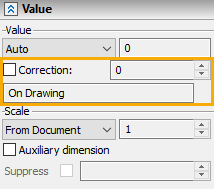
This parameter defines the correction value that will always be added to a dimension value. It is available only if the options Auto, Manual with Correction or By Source Lines are selected in the drop-down list of the Value parameter. If a scale is defined, the correction is added to the scaled dimension value. The correction value might be positive or negative. You can input it manually via keyboard or define via a variable.
The non-editable box below the Correction parameter displays information on how the dimension has been created:
•On Drawing – standard 2D dimension based on nodes or lines of a 2D drawing. The value of the dimension is calculated form the geometry of the drawing or specified manually;
•On Copy: On Drawing – dimension is based on elements of associative copy of nodes and the lines of a 2D drawing;
•On Copy: On Projection – dimension is based on elements of associative copy of 2D projection lines;
•On Projection – dimension is based on the 2D projection lines. If there is a 3D dimension based on faces of 3D model corresponding to such projection lines, and the From 3D parent option is selected for the Value parameter of the 2D dimension, then “(*3D)” is added to the informational string;
•On Operation – this text string appears for 3D dimensions drawn on the vertices, edges and faces of a 3D model (see the Dimension in 3D Scene section)
•Projected – this string appears for 2D dimensions created via projecting 3D dimensions (see the Projecting 3D Annotations section).

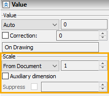
The scale factor, which provides control over the dimension value. For example, suppose, some portion of a drawing was performed in a different scale without splitting the drawing into drawing views. Since the units of measurement are the same throughout the drawing, you shall specify a scale factor for dimensions in the said portion of the drawing. Then the dimension value will be displayed according to the specified scale (that is, multiplied by the specified scale factor). The value of the scale is not taken into account if the Value parameter is set to Manual, From 3D parent or No. One of the following scale options can be selected in the drop-down list:

•Default. The scale is inherited from document parameters (Document Parameters > Page > Dimensions > Scale).
•None. The dimension doesn't have a scale factor.
•Inches/Millimeters, Millimeters/Inches. These are the standard scale factors introduced for the user convenience. When selecting one of those options, the appropriate scale factor is set automatically to make the conversion to other units.
•Custom. This option is used, when it is necessary to set an arbitrary scale factor. The factor value is entered in the input bo to the right of the drop-down list. For example, the case shown on the figure at the right has the scale factor equal to "5" for both dimensions (the top dimension also having the correction of "-400").

Auxiliary dimension
Enabling this checkbox makes the dimension auxiliary. Auxiliary dimensions are non-printable. In the drawing window they are displayed in light blue color. See more in the Auxiliary Dimensions section.
This parameter is only available for driving dimensions. Enabling the checkbox suppresses the dimension. A suppressed driving dimension works like a generic informational dimension, i.e. it doesn't affect the geometry of drawing, and dimension value changes in accordance with geometry changes, when editing the geometry. Upon disabling the suppression, the dimension becomes driving again, and its value gets restored to the one existed at the moment of enabling the suppression. Aside with the checkbox there is the input box. Disabled checkbox corresponds to the "0" value in the input box, enabled checkbox corresponds to the "1". A value can be typed into the input box manually or defined via a numeric variable, in order to control the suppression through parametrization. Any inputted value above "1" gets replaced by "1". Any inputted value below "1" gets replaced by "0".