Hole Table |
  
|
Icon |
Ribbon |
|---|---|
|
Title Block > Hole Table > New |
Keyboard |
Textual menu |
<THR> |
Title Block > Hole Table > New |
It creates a table containing the list of holes and their parameters. Hole table may be useful, when a drawing contains too many holes of various types, so it's hard to fit all necessary dimensions. The table contains data on all cylindrical holes created in various ways (via the ![]() Hole command, via the
Hole command, via the ![]() Extrusion command using
Extrusion command using ![]() Boolean subtraction, holes in imported geometry etc.), as well as data on holes with conical thread created via the
Boolean subtraction, holes in imported geometry etc.), as well as data on holes with conical thread created via the ![]() Hole command. Holes are taken into account, only if they're visible on selected 2D projection.
Hole command. Holes are taken into account, only if they're visible on selected 2D projection.
The command becomes available upon creating at least one 2D projection.
Upon calling the command, perform following actions:
1.Specify a type of table (coordinate or symbol).
2.Select one (for coordinate table) or multiple (for symbol table) 2D projections.
3.Specify a set of columns (optional action).
4.Specify a set of symbols to be used (optional action, available only for symbol table).
5.Confirm the specified parameters (![]() or <Ctrl>+<Enter>).
or <Ctrl>+<Enter>).
6.Set a local coordinate system (only for coordinate table).
Hole tables are based on the special type of product composition.
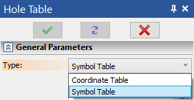
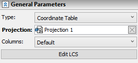
In the Type drop-down list located at the top of the command's parameters window you can select one of the following types:
•Symbol Table
When creating such table, standard symbols are put above the image of each hole on 2D projection. Each symbol corresponds to a particular set of hole's geometrical parameters. the table indicates, which symbol corresponds to which parameters.

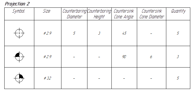
Symbol table and 2D projection with corresponding symbols
•Coordinate Table
When creating such table, you have to set a local coordinate system (LCS). Then coordinates of each hole's center will be calculated using such LCS and included into the table.

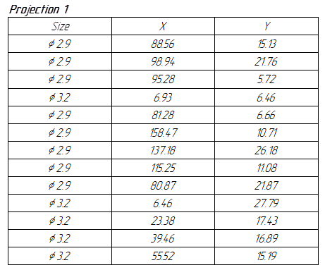
Coordinate table and 2D projection with corresponding LCS
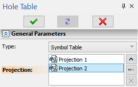
Upon selecting a type of table, you should select 2D projections, whose holes will be listed in the table. In order to select a projection, move the cursor over it and press ![]() . The name and icon of the selected projection will be displayed in the Projection list in the parameters window. Projections in the list can be selected using
. The name and icon of the selected projection will be displayed in the Projection list in the parameters window. Projections in the list can be selected using ![]() . You can
. You can ![]() Collapse,
Collapse, ![]() Expand,
Expand, ![]() Clear the list or
Clear the list or ![]() Delete element from the list using buttons located to the right..
Delete element from the list using buttons located to the right..
Only a single projection can be selected for coordinate table; any number of projections can be selected for symbol table.
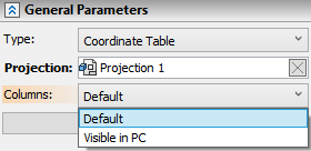
You can select one of the following options in the Columns box of the parameters window:
•Default
A symbol table will contains such columns as Symbol, Size, Counterboring diameter and Quantity.
A coordinate table will contains such columns as Size, X, Y and Counterboring diameter.
A default set of columns can be changed by replacing a report template in the product composition parameters. Default templates are stored in the T-FLEX Parametric CAD 17\Program\ProductStructs\ReportTemplates folder.
•Visible in PC
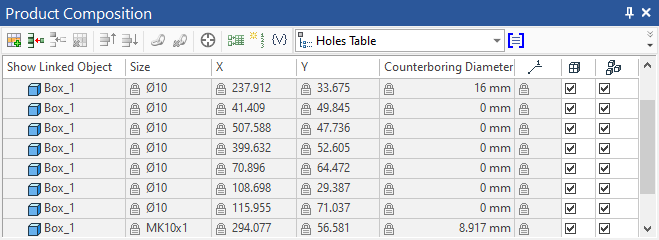
The table will contain the same set of columns as the one currently displayed in the ![]() Product Composition window, except service columns. A symbol table will additionally contain the Symbol column. By default, the
Product Composition window, except service columns. A symbol table will additionally contain the Symbol column. By default, the ![]() Product Composition window displays just a small portion of the full set of columns stored in the holes table data. Select the desired columns using the
Product Composition window displays just a small portion of the full set of columns stored in the holes table data. Select the desired columns using the ![]() button located at the top right corner of the
button located at the top right corner of the ![]() Product Composition window or using the contextual menu of columns' header. Alternatively, you can customize visibility of columns in the product composition parameters dialog.
Product Composition window or using the contextual menu of columns' header. Alternatively, you can customize visibility of columns in the product composition parameters dialog.
if a table uses the Visible in PC option, then its set of columns can be edited later using the report parameters dialog.
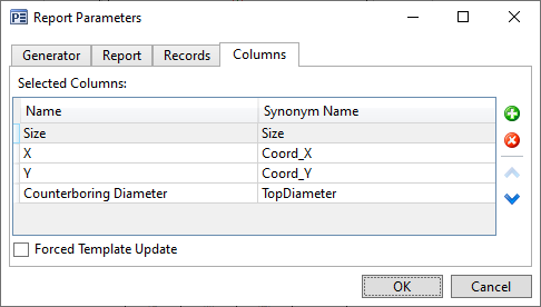
The dialog is invoked by pressing a table with ![]() and selecting the Report Parameters in the appeared contextual menu.
and selecting the Report Parameters in the appeared contextual menu.
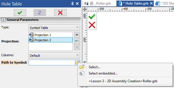
By default, symbol table uses symbols based on the parametric 2D fragment stored in the T-FLEX Parametric CAD 17\Libraries\System\Hole Symbols\Hole Symbol.grb file.
Path to the symbols file is displayed in the Path to Symbol box of the parameters window. You can select a different file using the ![]() Open button, which is located at the right edge of the input box. If none there are no open saved documents, then pressing this button invokes a file selection dialog of the current operating system. Otherwise it invokes the drop-down menu, which contains a list of open documents and following buttons:
Open button, which is located at the right edge of the input box. If none there are no open saved documents, then pressing this button invokes a file selection dialog of the current operating system. Otherwise it invokes the drop-down menu, which contains a list of open documents and following buttons:
•![]() Select
Select
Invokes a file selection dialog of the current operating system.
•![]() Select embedded...
Select embedded...
Invokes a list of embedded files, if there are such files within the current document.
Symbols file should contain a parametric 2D fragment with following external variables:
•x1 - Х coordinate of a hole center;
•y1 - Y coordinate of a hole center;
•d - diameter of a hole;
•index - index, which change shape and/or color of the symbol.
When creating a coordinate table, upon selecting a 2D projection, you have to set a local coordinate system to be used for calculating coordinates of holes. LCS for holes table is created using the parametric 2D fragment stored in the T-FLEX Parametric CAD 17\Libraries\System\Hole Symbols\Holes LCS.grb file. If selected 2D projection already contains such LCS (which is possible after deleting previously created coordinate table), then you can edit it using the Edit LCS button located at the bottom of the command's parameters window. Editing of an existing LCS is performed similarly to creating a new one.
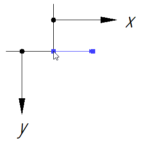
If selected 2D projection doesn't contain LCS for holes table, then, upon confirming the input via ![]() or <Ctrl>+<Enter>, a fragment insertion will be launched. The preview of the LCS will follow the cursor. You have to specify two points defining fragments fixing vector. In order to specify such points, move the cursor over desired position and press
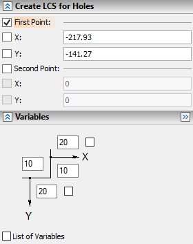
or <Ctrl>+<Enter>, a fragment insertion will be launched. The preview of the LCS will follow the cursor. You have to specify two points defining fragments fixing vector. In order to specify such points, move the cursor over desired position and press ![]() , or type the coordinates in the Create LCS for Holes tab of the parameters window. Below there is also the Variables tab (fragment's external variables dialog), where you can customize the LCS symbol. Numerical input boxes define length of corresponding elements of the symbol; checkboxes invert direction of axes. Set the desired parameters of the LCS and confirm the input again via
, or type the coordinates in the Create LCS for Holes tab of the parameters window. Below there is also the Variables tab (fragment's external variables dialog), where you can customize the LCS symbol. Numerical input boxes define length of corresponding elements of the symbol; checkboxes invert direction of axes. Set the desired parameters of the LCS and confirm the input again via ![]() or <Ctrl>+<Enter>. Next, you'll have to place the table in drawing.
or <Ctrl>+<Enter>. Next, you'll have to place the table in drawing.
Upon setting all necessary parameters, you should confirm the input.
In result, if the current page already contains a holes table of the same type, the new table will instantly replace the existing one, and work with the table creation command will end.
If the current page doesn't contain a holes table of the same type, then the preview of the new table will appear. The preview is a blue contour, whole top left angle follows the cursor.
The height of the preview doesn't represent the actual height of the resulting table, because the number of rows is calculated later.
Place the cursor into the desired position and press![]() . The table will be created.
. The table will be created.
Holes table product composition and report template
Holes table is a report based on special product composition. If there's no product composition of a Holes Table type in a document, it is created automatically upon calling the holes table creation command. The composition collects data on holes visible on each 2D projection on each page of the document. It recognizes cylindrical holes created in various ways and holes with conical thread created via the ![]() Hole command. If a same hole is visible on multiple projections, then a product composition will contain multiple records based on such hole, depending on the number of projections. Information related to countersink and counterboring is available, only if such elements are created via the
Hole command. If a same hole is visible on multiple projections, then a product composition will contain multiple records based on such hole, depending on the number of projections. Information related to countersink and counterboring is available, only if such elements are created via the ![]() Hole command.
Hole command.
Upon selecting a projection, the holes table creation command collects only those records of product composition, which are related to the selected projection. Holes are taken into account, only if they are visible considering the current projecting direction. Holes represented by hidden lines are ignored.
By default, holes table uses standard report template stored in the T-FLEX Parametric CAD 17\Program\ProductStructs\ReportTemplates\HoleReports folder. You can create a custom template, if necessary, and replace a template for an existing table in the report parameters dialog. Moreover, a table placed in drawing can be edited, using standard T-FLEX CAD table editing tools, but changes made this way will be lost upon regenerating the table.
A holes table product composition may also be created without placing a table in a drawing. It can be done using the following command:
Icon |
Ribbon |
|---|---|
|
Title Block > Hole Table > Hole Table Data |
Keyboard |
Textual menu |
<THS> |
Title Block > Hole Table > Hole Table Data |
Holes table product composition data is handled using standard T-FLEX CAD product composition management tools.
If you need to exclude from a table some of the holes included into product composition, disable the ![]() Include in report/BOM of current document checkbox in the
Include in report/BOM of current document checkbox in the ![]() Product Composition window for such holes. Upon selecting a record in the
Product Composition window for such holes. Upon selecting a record in the ![]() Product Composition window, its linked hole gets highlighted on 2D projections and in 3D scene. Coordinates of holes are only filled upon placing a coordinate table in drawing, because a coordinate system is not specified until placing a table.
Product Composition window, its linked hole gets highlighted on 2D projections and in 3D scene. Coordinates of holes are only filled upon placing a coordinate table in drawing, because a coordinate system is not specified until placing a table.
