Create 3D Weld > Butt |
  
|
To create a butt 3D weld, you need to perform following actions, upon calling the ![]() 3D Weld command:
3D Weld command:
3.Select source elements and define geometrical parameters of weld;
4.Define length of weld (optional step);
5.Enable the automatic mate creation (optional step);
6.Define basic parameters and side processing (optional step);
7.Confirm the weld creation (![]() or <Ctrl>+<Enter>).
or <Ctrl>+<Enter>).
When creating a weld, you may also use dynamic preview and preview of operation result.
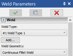
The type of weld can be selected in the Weld Type drop-down list located at the top of the Weld section of the command's parameters window. The list contains all types of welds created in the current T-FLEX CAD document.

If the required weld type is not yet created, you can use the button Add. Clicking this button starts the command of the new weld type creation. When the type is created, the system returns to the weld creation command. The created weld type will be automatically selected.
How to create a new weld type is described in the Weld Type section.
In addition to the user-created weld types, the list also contains the Non-Standard option, which allows creation of a weld not belonging to any type.
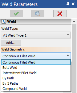
Select a geometry type using the Weld Geometry drop-down list located in the upper part of the Weld section of the command's parameters window.

Following geometry types are available:
•Butt
The Compound Weld option is not available in the list, if the Weld Type field specifies Non-Standard.
Source Elements and Geometrical Parameters
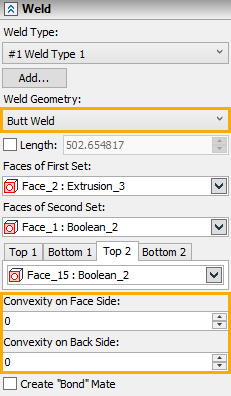
Upon selecting the Butt Weld option in the Weld Geometry drop-down list, the following options become available in the automenu, so you should select two sets of faces in the same way, as when creating fillets welds:
|
<1> |
Select Faces of First Set |
|
<2> |
Select Faces of Second Set |
The first option gets activated automatically on appearance, the second option gets activated automatically, upon selecting a face belonging to a different body, compared to faces previously selected using the first option. Selected faces are put into lists Faces of First Set and Faces of Second Set in the weld section of the command's parameters window. To remove some face from a selected set, pick it in the respective list by clicking ![]() , and then click the button
, and then click the button ![]() .
.
Additionally, there will be the options in the automenu to select the top and bottom faces of the bodies being welded:
|
<T> |
Select Top Faces of First Set |
|
<B> |
Select Bottom Faces of First Set |
|
<Y> |
Select Top Faces of Second Set |
|
<N> |
Select Bottom Faces of Second Set |
The selected faces are put into lists Top 1, Top 2, Bottom 1, Bottom 2. To remove some face from the selection, pick it in the respective list by clicking ![]() , and then click the button
, and then click the button ![]() .
.
In the case of the butt weld, you can also specify Convexity on Face Side (that is, the contour type of the weld on the side of the top faces) and Convexity on Back Side (the contour type of the weld on the side of the bottom faces) in the parameters window.

The method of calculating the weld length is determined by the state of the Length checkbox located below the list of weld geometry types. When the checkbox is disabled, the weld length is calculated by the system automatically. When the checkbox is enabled, the length value is defined by the user in the input box next to the flag.
If you enable the Create "Bond" Mate checkbox located at the bottom of the Weld section of the command's parameters window, then, upon weld creation, the mate of the "bond" type will be created automatically between the parent bodies of the selected faces.
Basic Parameters and Side Processing
When using a user-created weld type, the parameters window contains the Basic Parameters, Face Side Processing and Back Side Processing sections. the content of these sections is the same as described for 2D welds. When using the Non-Standard weld type option, these sections are not available.
Parameters set in Basic Parameters, Face Side Processing and Back Side Processing sections are used for creation of weld symbols.
See Also: